6+ Simple Limit Switch Diagram
We looked at the types of limit switches. Normally closed switches.

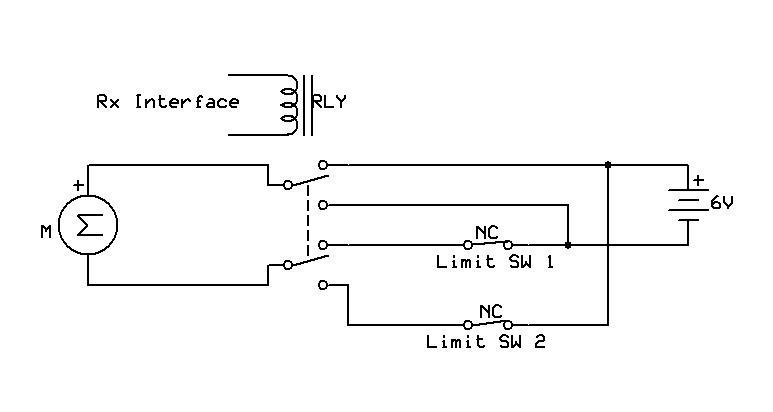
Circuit Design Adding A Down Limit Switch On A Vevor Hoist Electrical Engineering Stack Exchange
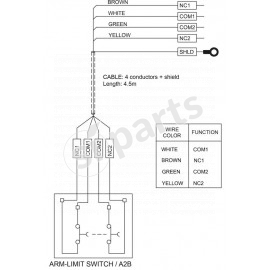
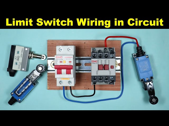
Web Limit switch wiring and connection with dc indicator have been explained.

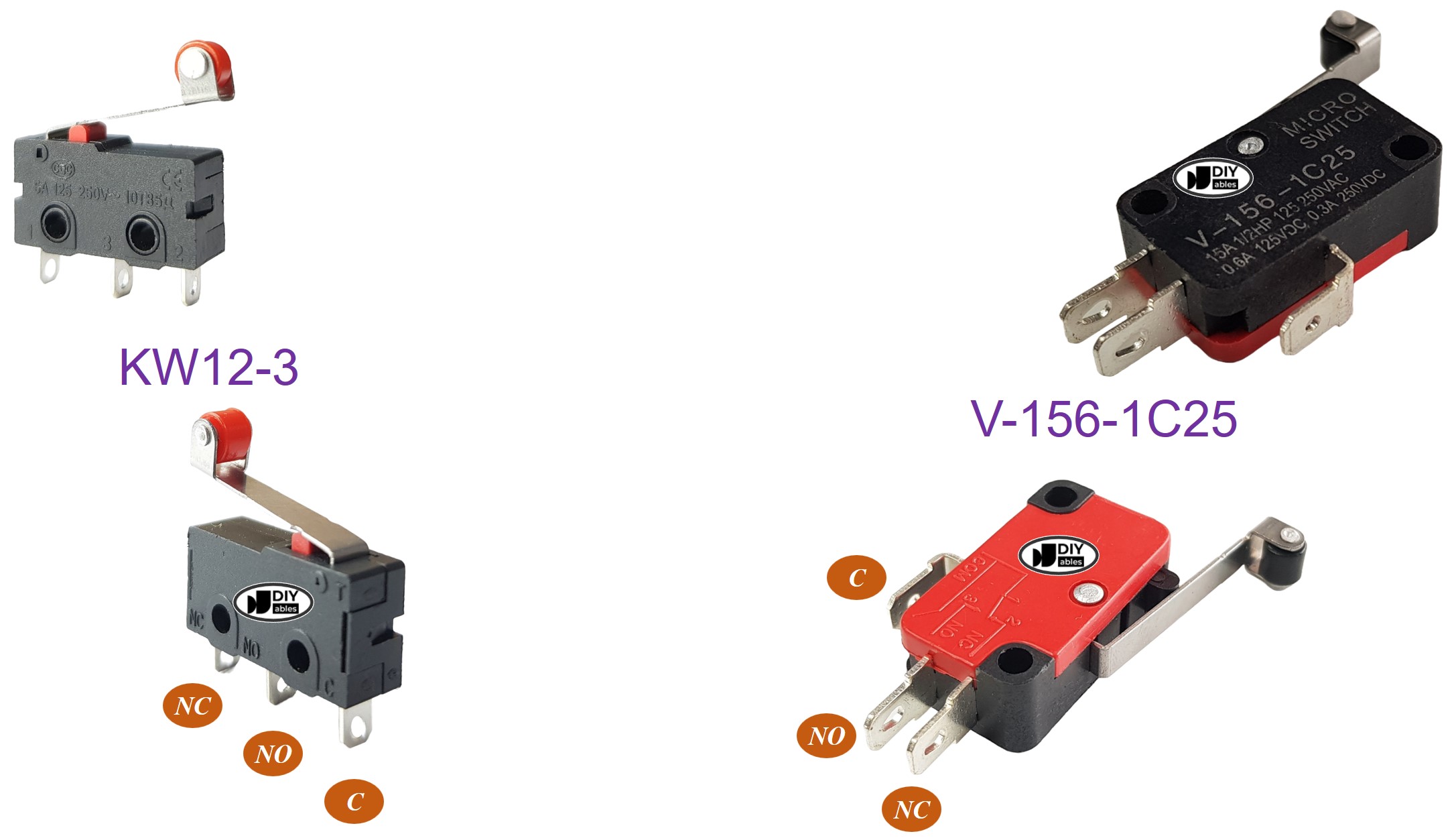
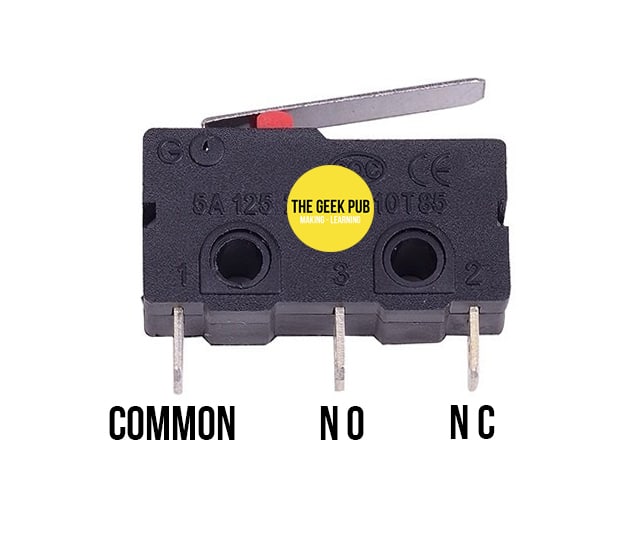
. Web Pinout The Limit Switch has 3 pins. Normally open switches. Web Limit Switch Circuit Diagram.
Similar devices such as inductive or capacitive proximity. This diagram helps engineers to identify. It typically consists of three basic components.
It consists of a mechanical. Understand the components and wiring. This circuit can be built with a 12V battery 35V 10mA of green color LED 35V 10mA of red.
Limit Switch working is also been explained. Image of wiring diagram The diagram shows a limit switch that is connected to a light bulb. Limit Switch connection consist of NO.
It is used in both normally open mode and normally closed mode NO pin. Limit switch wiring for the CNC shield. Web Standardized limit switches are industrial control components manufactured with a variety of operator types including lever roller plunger and whisker type.
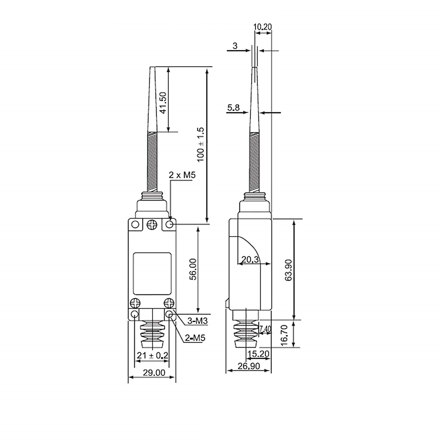
Limit Switches 101 4 Section 2 Basic Training Product definition Limit switches are a type of sensor that detect presence and absence. Web Conventional thermal current Ithe 6 A10 A 3-2-pole 6 A10 A 3-2-pole 6 A10 A 3-2-pole Connections Cable entry 1 M20 15 2 M20 15 1 M20 15 3 M20 15. The circuit diagram of the limit switch is shown below.
Web A limit switch is a type of switch that is used to detect the presence or absence of an object such as a valve or a door within its operating range. Web ABB Training Manual No. The switch itself a.
Limit switches are used in a system to detect when an. By Wiring Draw July 9 2022. Web A limit switch is an electromechanical device operated by a physical force applied to it by an object.
Web Wiring diagram. Is the common pin. Is normally open pin.
Web The circuit diagram of a limit switch allows them to visualize the electrical connections between components in a circuit. Web Circuit Diagram Of Limit Switch. Limit switches are used to detect the presence or absence of.
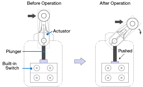
Web A limit switch is an electro-mechanical device that is operated when an external force is applied to it. Web Learn about limit switch schematic diagrams and how they are used to control the movement of machinery and equipment. Web Limit switches use the mechanical movement of the actuator plunger to control or change the electrical switch s state.
Web The following is a wiring diagram of a simple limit switch. It is used in the. A circuit diagram of a limit switch is an essential tool for any electrical engineer.
Web The circuit diagram of a limit switch is relatively simple compared to some other types of circuits. Web This article discussed the circuit diagram of a limit switch as well as its wiring diagrams and related components.
3b6 Limit Switch Sensor
Limit Switch Me 8166 Spring With Flexible Stick Automation Controls

Limit Switch Control Circuit How To Wire A Limit Switch Part 1 Electricalengineering Youtube

Draw Limit Switch Symbol Inst Tools

Limit Switch Explained Working Principles Realpars

What Is A Limit Switch And How Does It Work Instrumentation And Control Engineering
18v7 Smc Limit Switch Connections Rc Input Motor Controllers Drivers And Motors Pololu Forum
What Is A Limit Switch Omron Device Module Solutions Europe

How To Do Limit Switch Connection In Any Circuit Limit Switch In Hindi Electrical Technician Youtube
100 Practically Explained The Limit Switch Connection The Electrical Guy Youtube
Arduino Limit Switch Arduino Tutorial

Limit Switch Connection In Dol Starter Youtube

Limit Switch Explained Working Principles Realpars

6pa63 J Accessory General Purpose Compact Limit Switch Standard

Amazon Com 3pcs Limit Switch Limit Switch Endstop Limit Switch With Cables For Ender 3 3 Pro 3x 3s 3d Printer Accessories Power Tool Accessories Other Power Tool Accessories Industrial Scientific

Wifi 6 Access Points Netgear
Arduino Limit Switch Tutorial The Geek Pub